South Dakota Mines RAMADDA Data Repository Login Help |
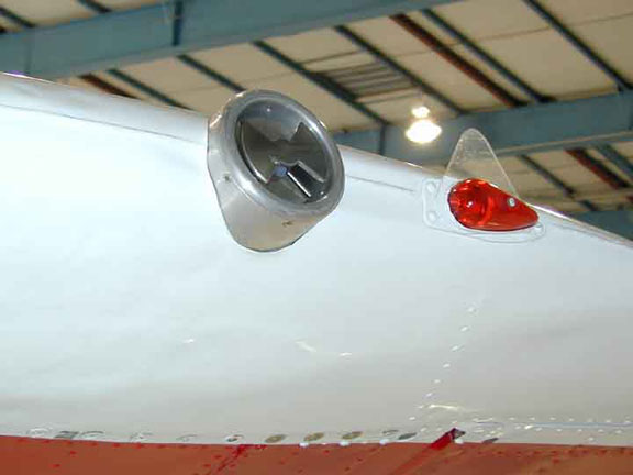
Electric FieldsThe three-dimensional ambient electric field components can be obtained from a suite of 6 rotating-shutter electric field meters mounted on the T-28 (one on the rear canopy facing upward, one on the lower fuselage facing downward, one on each wing tip facing outward, and two in a pylon on the port wing facing downward). Winn (1993) describes the meters themselves. The performance of this system is periodically checked by artificially charging the aircraft in clear-air flight using an on-board high voltage power supply. The equations used to calculate the ambient electric field components usually should produce good results in the absence of interference from the effects of aircraft charging. Mo et al. (1999) demonstrate that the aircraft is rarely charged highly, as corona discharge from trailing edges of the propeller and airframe, and discharge wicks placed on the trailing edges limit buildup of aircraft charge. A more serious problem is the effect of the space charge due to corona discharge from the propeller on the two fuselage meters. Mo et al. (1999) discuss how the effects of this charge can be detected and eliminated during calculation of ambient fields from the meter readings. Below is the electric field meter on the port wing tip.
Figure 17: NMIMT Model 100 electric field meter in port wing tip of T-28. |